The compass-clinometer is used to measure: (1) the orientation of geological planes and lineations with respect to north; and (2) the angle of dip of geological features with respect to the horizontal. This allows an accurate record of the geometry of the features to be constructed. The compass-clinometer can also be used in conjunction with a topographic map to accurately determine location.
There are two main types of compass-clinometer design on the market: the first type is made by Brunton, USA, Freiberger, Germany and Breithaupt, Germany; the second type is made by Silva and Suunto, both based in Sweden. The Brunton-type compass-clinometer is a more sensitive device because of the in-built spirit levels and the graduation of the scales in 1° rather than 2° increments. The Brunton-type can also be used for more tasks (see below); however, it is bulkier, more expensive and for some functions more difficult to use. The accuracy of the Silva-type compassclinometer is sufficient for most purposes and is much better designed for directly transferring compass directions to a map. Because the design of the two compassclinometers is different, their operation for some measurements is also different. Instructions for both types of compass-clinometer are provided in this section.

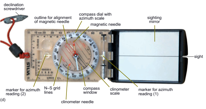
The compass-clinometer is both a magnetic compass and a device to measure the magnitude of the angle of dip of a surface from the horizontal. In order to do this, it has two needles and two quite different scales (Figure 2.3 b and d). When the compass-clinometer is orientated with the compass window horizontal, the magnetic needle will always point towards magnetic north–unless, that is, there is another magnetic body that is affecting it, such as your hammer, a metal pen, or a large magnetic body of rock. In addition, if you are at very high latitudes, compasses do not work well. Associated with the magnetic needle is a circular dial on the outside of the compass window that provides a measure of the azimuth in degrees away from north. The azimuth method for determining direction uses a circle with the value increasing clockwise from north at 0 ° ( = 360 ° ). On the Silva – type the dial can be rotated to place the needle at 0 °. The azimuth reading for the direction in which the sight at the end of the mirror is pointing can be read off using the ‘ marker for azimuth reading (1) ’ (Figure d). Note that because the azimuth scale is fixed in the Brunton-type and the needle moves relative to this, the compass is numbered and labelled anticlockwise. The azimuth for the direction in which the long sight on the Brunton-type is pointing (Figure b) is the reading at the north end of the compass needle. Compass directions from north can either be reported approximately, e.g. northwest, east, etc., or to the nearest degree. The Brunton-type compass also has a built-in locking pin for the magnetic needle to temporarily hold the needle in place when a reading is taken (Figure c).

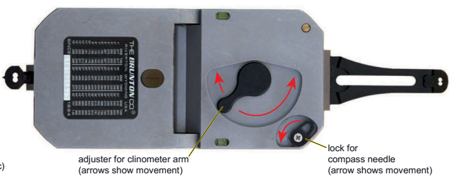
The design and working mechanism of the clinometer part of compass -clinometers varies between the different makes and models. However, the principle of the clinometer is exactly the same. On both types of compass there is a scale on the inner part of the compass window to measure the magnitude of the angle between the needle and the horizontal (clinometer scale; Figure b, d and e). To use the clinometer part, the instrument needs to be held with the compass window vertical and the long edge at the same angle as the dipping surface. In the case of the Brunton-type, the long edge adjacent to the east on the azimuth scale needs to be at the base because of the way the clinometer scale is orientated. The Brunton-type compass has a clinometer arm, the position of which can be adjusted using the lever on the back of the device (Figure c). When it is correctly adjusted for a particular dip angle the bubble in the long level should be in the centre. In contrast, the Silva- type has a clinometer needle that floats free and vertically downwards when the device is held on its edge vertically. The clinometer needle will hold its position if the instrument is carefully tilted about 20° from the vertical to the horizontal. To measure the dip on the Silva-type the compass dial needs to be set so that (i) the ‘marker for azimuth reading (1)’ (Figure d) is at 90° or 270° and (ii) the long edge of the compass -clinometer is orientated so that the clinometer scale is at the bottom where the clinometer needle is located. It may help to think of the clinometer as a protractor within the compass housing with a plumb line (the needle) indicating the magnitude of the angle relative to the horizontal. To test how your model works try holding the compass-clinometer as if it was on a horizontal plane and then increasing the angle to 45° and then to 90°. The operation of both types of compassclinometer for specific applications is explained and illustrated later in this section.